The Binospec spectrograph has been commissioned at the MMT telescope in fall 2017. Binospec is a multislit imaging spectrograph with two 8' x 15' fields of view, wide wavelength coverage, and high efficiency. There are two identical all-refractive spectrographs, one for each field. Each channel has several gratings and filters.
This page provides preliminary information about Binospec for potential users and proposers. Binospec was successfully commissioned in fall 2017 and is scheduled for shared-risk science observing in spring 2018.
Each side has a 4K x 4K deep depleted E2V CCD detector with 15 micron pixels and a scale of 0.24 arcsec/pixel. The resolution per pixel is tabulated below. The wavelength coverage of a slitlet depends on the distance from slitlet to optical axis along the X direction (along the short side of the masks). From near (central) side of the mask to the far side, the change in coverage is approximately 900 A to the blue for the 600 gpm grating.
Slitmasks are machined by a laser cutter at SAO (eventually to be relocated to the MMT). Slitmasks are designed by users with the BinoMask software, written at SAO, and running on a server hosted at the MMT. Users log into a web interface to interactively design masks and submit them. Masks must be configured ahead of a Binospec run to allow time for machining. Premade masks with long slits are also provided; the widths available are 0.75", 1.0", 1.25", 1.5", and 5". One long-slit mask will always be loaded, typically the 1.0". If different long-slit widths are needed, please request these widths in your target catalog submission so they can be loaded ahead of time. The longslit masks have one slit for each side of the instrument, so typically your target will be in one side while the other slit is pointed somewhere about 10 arcminutes away. 10 slitmasks can be loaded simultaneously, but two slots will always be occupied by imaging and longslit. Masks can be changed during each afternoon.
Using a typical/standard wavelength setting will help in obtaining standards and calibrations. For wide wavelength coverage, the 270 line grating with a central wavelength of 6500 A is a good choice.
| Grating lines/mm | Order | Blaze angle | Angle of incidence | Anamorph Demag. | Coverage (A) | Dispersion (A/pixel) | Pixels per 1'' slit | Resolution in 1'' slit |
|---|---|---|---|---|---|---|---|---|
| 270 | 1 | 5.5 | 28.0 | 1.08 | 3900-9240 | 1.30 | 3.75 | 1340 |
| 600 | 1 | 16.0 | 33.2 | 1.17 | 4500-6960 | 0.60 | 3.47 | 2740 |
| 600 | 1 | 16.0 | 36.1 | 1.22 | 6000-8480 | 0.61 | 3.32 | 3590 |
| 600 | 1 | 16.0 | 38.5 | 1.27 | 7255-9750 | 0.61 | 3.20 | 4360 |
| 1000 | 1 | 13.75 | 37.1 | 1.24 | 3900-5400 | 0.36 | 3.27 | 3900 |
| Grating lines/mm | Allowable central wavelengths |
|---|---|
| 270 | 5501 - 7838 A (approx 6560 A for full wavelength coverage) |
| 600 | 5146 - 8783 A |
| 1000 | 4108-4683, 5181-7273, 7363-7967, 8153-8772, 8897-9279 |
| Ghosts may be troublesome with 1000 gpm grating at
central wavelengths 5600-8500 A, worst near 7100 A. Throughput of 1000 gpm grating will be low in the red. |
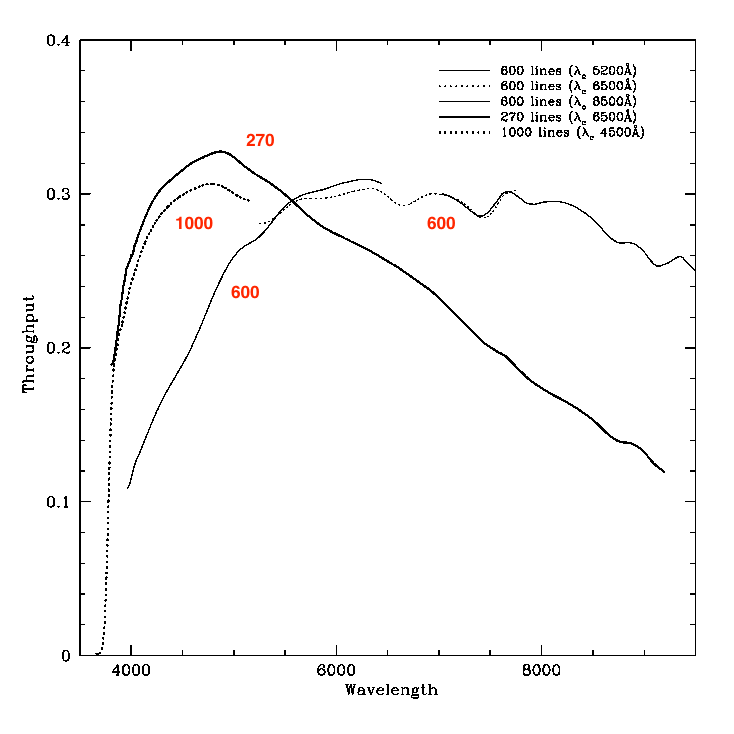
Binospec is expected to be several times more efficient than Hectospec due to throughput and improved sky subtraction. Here are on-sky throughput measurements made with the three gratings during commissioning. These include the telescope and corrector (a factor of about 0.81). There was light cirrus so the true throughput may be slightly higher. Three central wavelength settings are included for the 600gpm grating.
SAO has built a preliminary exposure time / sensitivity calculator for Binospec and Hectospec, written by Michael Kurtz. Relevant information is on several webpages:
For imaging see this calculator (select MMTcam): http://www.cfa.harvard.edu/mmti/megacam/obs_manual/exptime.html
For standard stars and similar calibrations, be careful not to saturate the detector. A preliminary suggestion is an exposure of 15 seconds for a typical spectrophotometric standard at V=11. Please be aware that accurate coordinates in the Gaia frame and proper motions are necessary for standards; many standards have high proper motions. Please see the MMT spectrophotometric standards page for the list of "ESO spectrophotometric standard stars" with up to date Gaia proper motions.
For imaging, PLEASE limit exposures to 120-150 sec or less. A V=17 star will saturate in the g filter at 120 sec. Longer exposures saturate too many stars and cause persistence in the CCD that can last for hours, which appear as artifacts in faint spectroscopic observations. This degrades your data and the data of other observers who come after you.
A model of the optical train of Binospec is shown below, illustrating the single slitmask at the top, and the paired spectrographs, filters, gratings, and detectors.
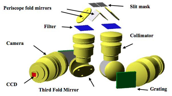
Optical train of Binospec.
The paired fields of view on the sky are shown below in green - the separation between them is 3.2 arcmin. The yellow boxes are the guider patrol regions, and the blue box is the wavefront sensor patrol region. The slitmasks cover the guider regions and holes are machined into into the masks at the location of guide stars, to allow for slitmask alignment and guiding.
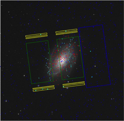
Binospec on the sky. Green rectangles are the spectroscopic fields, yellow are the allowed positions for guide stars. The blue rectangle shows the wavefront-sensor patrol area. Red dots are targets; blue are guide stars; short cyan lines show the slits assigned to targets. Side B is the side that is farther from the wavefront sensor (blue box).
Binospec observations are done in a queue, similar to Hectospec and MMIRS. The queue is administered by MMT staff and the instrument is usually operated by MMT queue observers. PIs/guest observers will typically not need to come to the telescope. PIs submit observing catalogs and mask designs through the MMT queue scheduling interface. Prior to the run, PIs will get an email asking them to log in to the queue scheduler to upload catalogs and observation details. During the run, PIs can log in to see progress on their programs and download data. For more information about the queue catalogs, see the help page for the MMT queue catalog interface.
Binospec can hold 10 slitmasks, and these can be changed out freely during the day (unlike MMIRS). However, there is a lead time for machining masks, and we typically have a mask deadline ahead of the first Binospec run of a trimester.
The grating tilt controls wavelength coverage. A standard grating tilt for full coverage is the 270 lpmm grating at central wavelength 6500 A. The 600 lpmm grating is optimized for the red, and the 1000 lpmm grating is optimized for the blue. Two long-pass filters are provided for spectroscopy, LP3500 and LP3800. These block light shortward of 3500 A and 3800 A respectively, and can prevent 2nd-order blue light from contaminating 1st-order red spectra (eg 2nd-order light at 3500 A on top of 1st-order light at 7000 A). They have essentially clear transmission longward of these wavelengths. Most observations can use the LP3800 filter; observers interested in spectra shortward of 3900 A can use LP3500.
The instrument can be changed from spectroscopic to imaging mode quickly, and has g, r, i, z filters for each side. We do not anticipate initially offering mixed observing between the sides (ie imaging + spectra, or two different gratings). Because the sides are pointed at separate fields on the sky, there is not a simultaneous-observation advantage for mixed modes.
The Binospec catalog page asks users to enter various parameters such as RA, Dec, grating or filter choice, exposure time, and so on. More description is available at the catalog help page. We recommend that:
Binospec uses guiders offset from the main field of view, patrolling the yellow box regions in the figure above. Guide stars can be selected automatically from GAIA (preferred) or GSC2 catalogs. Thus, it is absolutely necessary to supply coordinates that are on the GAIA or GSC2 system. The correct coordinate system is critically important for both longslit and slitmask spectroscopy.
Targets for longslit spectroscopy will be offset onto the slit by acquiring stars onto the guiders, whose positions have been calibrated relative to the slit. Thus, your target position needs to be on the same system as the guide stars. If you provide a target position that is on the Gaia system, the guiders can bring the target directly onto the slit without any extra effort. This is strongly preferred as the way of acquiring a target. The preferred method of acquisition is very accurate, but your coordinates must be good and on the Gaia system. If the target has significant proper motion, these must be provided! Many standard stars have high proper motions and epoch-2000 coordinates are well out of date in 2018. Please see the MMT spectrophotometric standards page for the list of "ESO spectrophotometric standard stars" with up to date Gaia proper motions.
Currently, it is not possible to acquire targets by a blind offset from a star. Rather, you can provide accurate coordinates in the Gaia system and Binospec will set accurately directly to your target. It may be possible in future to tune the pointing up by tilting the grating to zeroth order and taking a direct image of the target through the slit. This would work for objects brighter than some magnitude (R~21). For faint targets, PIs could provide a nearby offset star on the same coordinate system as the target. However, these modes are not in common use now and providing Gaia-frame coordinates is preferred. Finding charts and other useful information about the target can be entered in the "notes" section of your observing catalog.
Acquiring using a slit-viewing camera requires a "mirrored" slit mask whose use has not yet been commissioned, so good coordinates that allow the above procedure to work are a requirement.
For multi-slit masks, the PI provides a list of targets on GAIA (preferred) or GSC2 coordinate systems. The BinoMask slitmask design program adds suitable guide stars and cuts alignment holes in the slitmask, through which the guiders image the stars to tune up the alignment of the mask.
Note that Binospec is behind the f/5 ADC (atmospheric dispersion compensator). Thus, you do not need to observe at the parallactic angle for longslits or for slitmasks. For longslits, you are free to specify a desired position angle on the sky in your observing catalog. For slitmasks, the PA will be determined during mask design, and when you create an observing target from the slitmask, the RA, Dec, and PA in your catalog will be read from the mask design file.
Slitmask design is done by PIs using the BinoMask web based interface. Masks will be machined with a laser cutter at SAO (in future, on the mountain) by SAO staff. Masks need to be submitted well in advance of the start of queue observations for a semester.
Please see the BinoMask slitmask design interface tutorial webpage for a more detailed walkthrough of using the software.
You will be running a web-based mask making program called BinoMask which will take a text file as input, containing your targets to be observed. If your objects are on the GAIA coordinate system, binomask can add guide and wavefront-sensor stars for you. If not, you must create a second catalog with such stars on the same coordinate system as your targets, extending to at least 0.4 degree in radius from the center of your target field. For guide stars, please select a magnitude range of r=14-18; for WFS stars, magnitude r=11-14.
The format for the catalogs is an ASCII file with columns. You may separate entries either with a comma or a tab. The first line of the file is a header:
name, ra, dec, magnitude, priority, pm-ra, pm-dec, epoch, typeThe following lines contain entries for those columns.
Only ra and dec are required, but name, magnitude, & priority are also recommended. (1=highest priority, then 2, 3, etc). Coordinates may be in decimal degrees or sexagesimal. Type should be 1 (or “target”), 2 (“sky”) or 3 (“standard”).
A queue scheduling interface similar to the MMIRS user interface allows PIs to submit mask designs, track their program progress, and download raw data. The materials/machining cost for slitmasks will be determined at a later date.
Mask making is integrated with telescope scheduling software. Thus if you have been granted time, you will receive an email from scheduler@mmto.org with instructions to log in, make masks, and submit catalogs. For more information on queue catalogs, visit the help page for the MMT queue catalog interface. You may also use the mask making software outside of that framework. To run the BinoMask software visit scheduler.mmto.arizona.edu/BinoMask/. Slit widths are also set by the user. As an aid, the MMT web site states that the median seeing is in the range of 0.77" - 0.85" based on data from 2003 to the present. 1 arcsecond slits are a good starting point.
Note that the differential atmospheric refraction across the 15 arcminute field is significant, so that the location of slitlets depends on the hour angle at which the mask is observed. In practice this means that the mask machining would change slightly depending on whether the mask is observed when HA is East or West. Thus the date and time of observation specified during mask design are significant. Observable hour angles will be taken into account during queue scheduling.
You may get the error “slits can not be made” which often occurs because the rotator setting is not correct. Try adding or subtracting 180 from the present setting.
It is good practice to avoid mask position angles that run into the rotator limits (which are near +180/-180). Binomask will try to avoid PAs that hit the limits in the middle of your observing window. In practice, the limits mean that to avoid hitting the limit at transit, for masks that are north of the MMT (Dec > +33), you should avoid position angles near 0, and for masks south of the MMT (Dec < +33), you should avoid PAs near +180 or -180.
In order to obtain the maximum scientific impact from Binospec, we will to continue the queue scheduling that has proven successful with Hectospec, Hectochelle and MMIRS. Queue scheduling offers the considerable advantage that we can flexibly adapt the observing program to the current conditions. We will reserve conditions of perfect transparency and superb seeing for those projects that can take best advantage of excellent conditions. Queue scheduling also allows observations to be obtained at low air-mass and allows continuous observation of high priority objects. The instrumeht will be operated by MMT staff queue observers, and proposers are not generally expected to travel to the telescope.
Binospec raw data (fitsraw) and minimally processed data (fitsproc, overscan subtracted) are available shortly after an observing block is completed and can be downloaded from the PI's queue catalog interface. An observed target will show a small blue folder icon; clicking this icon brings up a window to select files for download. Imaging data can be reduced using standard astronomical techniques (IRAF, astropy/ccdproc, etc).
The Binospec spectroscopic pipeline is written in IDL by SAO staff, primarily Igor Chilingarian and Sean Moran, and is now publicly available. The pipeline code repository is at Binospec pipeline on Bitbucket. A brief description of running the pipeline and of the output data formats is at the Binospec pipeline repository wiki.
The pipeline uses some similar algorithms to the MMIRS pipeline. The SAO TDC is anticipated to return reduced data to the PIs. The timescale for data reduction is TBD. SAO and MMT staff are currently working on having the data quickly reduced and reduced data made available through the MMT queue observing catalog interface, similar to the way that raw data are downloadable. PIs will get an email when their reduced data is ready.
Availability of quick look reductions or quickly returning raw and reduced data are recognized as desirable for some programs. The pipeline includes a quick reduction routine, binospec_quicklook. A quicklook for queue observers to assess data quality is in progress.
Binospec raw data are stored as multiextension fits files; each CCD has 4 amplifiers, each of which is stored as an extension. Data taken are archived at the CfA. The raw and lightly processed (overscan and trimmed) data can be downloaded from your observing catalog. The processed data typically will have 2 fits extensions, one for each side of the instrument. For longslit data, your object will typically be in side B (extension 2).
The spectroscopic pipeline (now in a preliminary release), is used to process the data and provide wavelength calibrated, relative-flux corrected spectra. Currently, the queue observing system will send the PI a notification the day after any of your data is taken, at which time the PI may login to their queue observing page and download the raw data.
When the pipeline has been run and reduced data are available, the PI will receive another email. The data files are accessible through the MMT queue catalog management pages: each target that has been observed has a blue folder icon. Clicking the folder icon allows the PI to view available data files and download them. Imaging data are in a fairly standard format and will not be reduced by the pipeline, but can be reduced by standard techniques (eg IRAF, mscred, etc). The format of the pipeline-reduced spectrosopic data is described at the Binospec pipeline repository wiki. Example code to read the data is in progress.
   setenv SPECPRO_DIR /Users/bjw/idl/specpro
   setenv IDL_PATH :+${SPECPRO_DIR}/code:$IDL_PATH
   setenv IDL_PATH :+${SPECPRO_DIR}/external:$IDL_PATH
   setenv SPVIEW ${SPECPRO_DIR}/templates
but replace "/Users/bjw/idl/specpro" with the directory where you
installed specpro. If you use bash, use export SPECPRO_DIR=... instead
of setenv.
convert_binospec_to_specpro, 'obj_counts_slits_extr.fits', 'obj_counts_slits_lin.fits', outdir='specfiles'substituting the appropriate filenames as needed. This will make a 1-d file, 2-file, and info file for each slitlet (it's a lot of files) in the subdirectory. If you put the convert_binospec_to_specpro.pro file in the current directory, or if you get an undefined procedure error when running it, compile it first with the IDL command:
.com convert_binospec_to_specprothen run the convert_binospec_to_specpro command. As of Dec 2018 there is a new version on github that compiles all the subroutines when you run it, to avoid an undefined procedure error.
  cd,'specfiles'
  device, decomposed=1
  specpro_bino, 1, /basic
You only need to do the file conversion once per dataset, and can then run specpro for as many sessions as you like.
For more detailed information on a suggested workflow using Specpro, visit the Using Specpro to inspect Binospec data page. Running Specpro will let you look at 1-d and 2-d data, smooth it, enter trial redshifts, enter redshift quality estimates, save output, and step through the slits. Read the tutorial and manual on the Specpro website to understand the GUI features. Fitting for the best redshift now works with the revised zfindspec.pro. If you don't get a good redshift result or if the spectrum has bad data at the ends, redshift fitting can be improved if you click-and-drag in the 1-d spectrum plot window to zoom in on a 1-d spectral region containing emission or absorption features and excluding data problems.
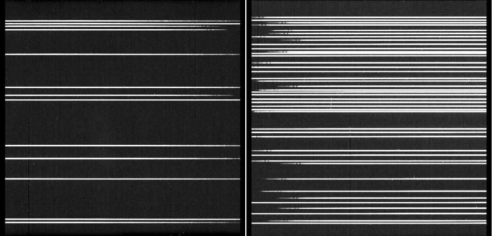
These images were taken during Binospec commissioning in fall 2017.
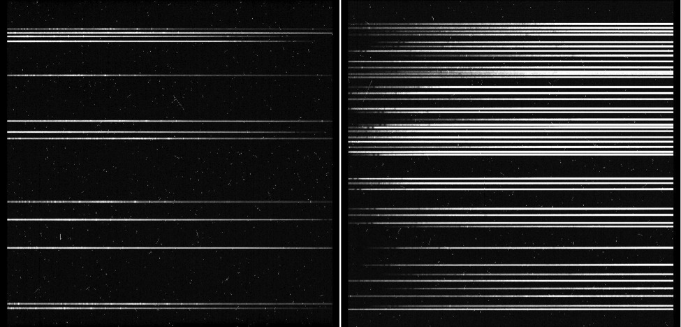
A multislit single exposure of 600 sec. Blue wavelengths are toward the center; red is to the left in the left frame and to the right in the right frame. Note the cosmic ray hits.
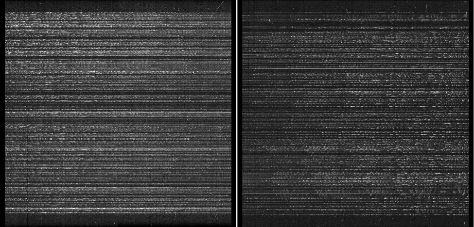
Combination of 4 exposures. Ca H and K absorption lines are visible as a doublet near the blue end of several spectra.
 >
>
A 600 sec single exposure on a mask with many short, 2 arcsec long slits, using the 600 gpm grating
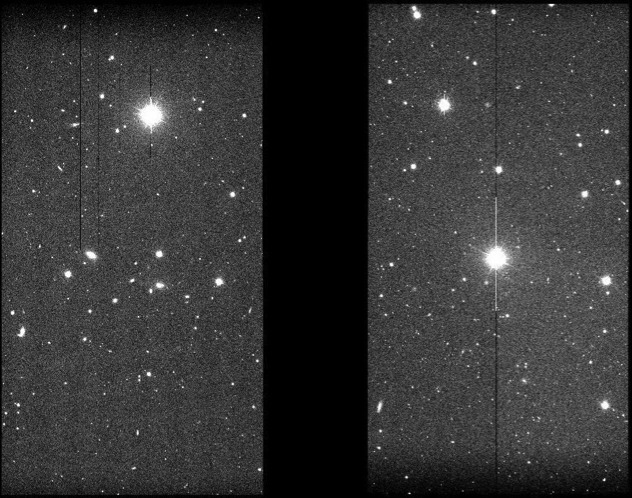
A direct imaging exposure, 50 sec in g band.
This page is updated with information from Binospec commissioning and the first few semesters of operations starting 2018A. Please contact Benjamin Weiner, bjw@mmto.org, for further information.